While not the most glamorous project-car task, wiring is crucial to a well-running vehicle. Here’re tips, tricks and best practices to make your next install a breeze.
Of all the unwelcome drama a performance vehicle can inflict on its owner, chasing electrical gremlins is perhaps the most frustrating. Just one little wire improperly installed can cripple a car’s performance if the vital engine functions—such as an O2 sensor—are connected to that circuit.

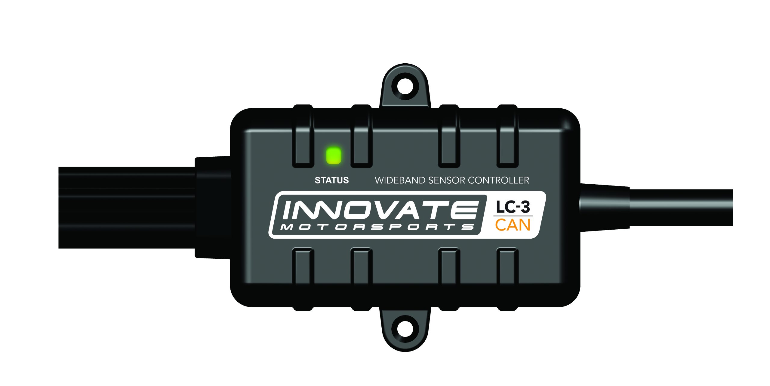
Innovate Motorsports, which manufacturers industry leading wideband controllers, data acquisition equipment, and both digital and analog gauges, says improperly installing its products could result in inaccurate displays, error codes and false information to the vehicle’s ECU or data logger. So, before any electrical problem triggers new adventures in aggravation and futility, the company suggests taking the time to understand the basics of wiring and electrical circuitry.
Do-it-yourselfers often look for the easiest solutions when installing parts. Such a practice is not always due to simple laziness. Some of this approach is driven by questionable advice from friends. Other times it’s relying on outdated methods that don’t apply to modern, sophisticated electrical platforms—even though the task at hand is simply finding a power source or a reliable ground connection.

“Customers tend to tap any 12-volt source on their vehicle without understanding there are multiple circuits on the car dedicated for specific purposes,” says Felipe Saez, customer service technical at Innovate Motorsports.
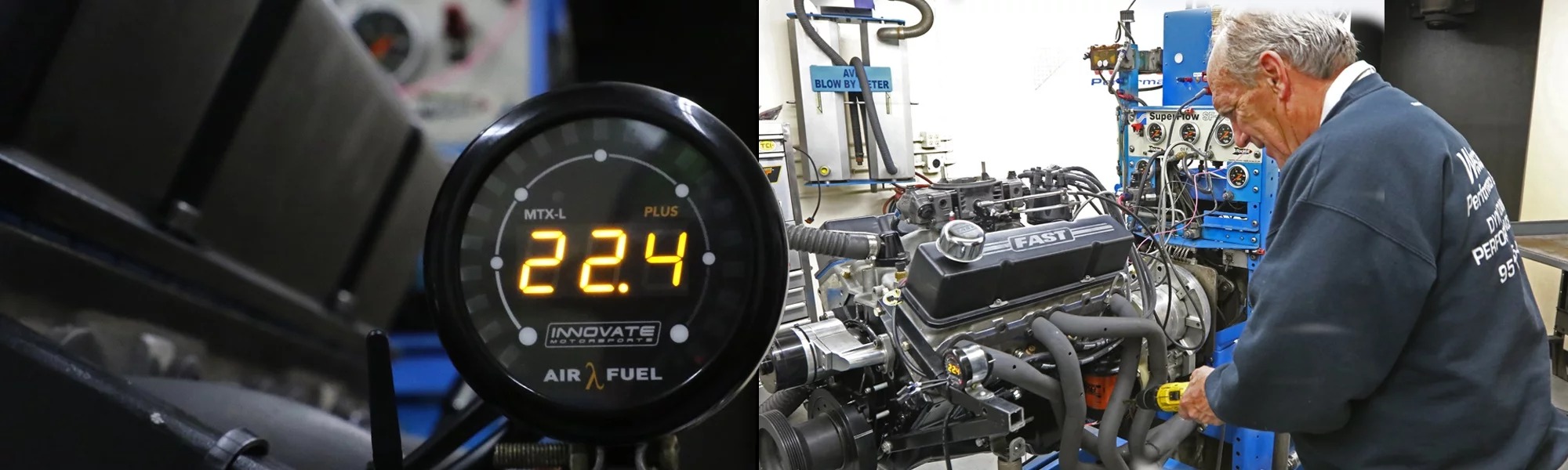
For example, the Innovate MTX-L Plus is an advanced, stand-alone wideband air-fuel controller and digital readout gauge. It uses a Bosch LSU 4.9 wideband O2 sensor and is compatible with several different fuels. Upon first glance it appears similar to a conventional sensor and gauge combination designed to give the driver specific information. However, the MTX-L Plus is much more sophisticated than a typical oil-pressure or water-temperature gauge. Remember, a wideband sensor requires a heating element that must be kept at the correct temperature to provide an accurate reading.
Within the gauge is a controlling unit that regulates the sensor’s heater. In other words, you can’t just apply 12 volts to the heating element and let it run. If the heating element isn’t at the optimum temperature for the engine rpm or load, then the feedback to the gauge or to an ECU isn’t accurate.

“The challenge with widebands, as opposed to an oil-pressure gauge, is that we’re heating up that O2 sensor and the power draw is significant,” says Saez. “An oil-pressure gauge may draw a half amp, and that doesn’t fluctuate. You just turn on the gauge and you’re receiving information from the sensor.
“With the MTX-L Plus, we’re heating up the O2 sensor, and the amperage draw changes,” continues Saez. “It changes at wide-open throttle because there is more exhaust flow going over the that sensor. Therefore, the heating has to ramp up. But when you’re cruising around, the draw isn’t that much. But you still need headroom for those changes.”

Now is a good time to refresh memories on the basics of electrical current, which is defined in simplest terms as the flow of electrons through a conductor. Voltage is basically the pressure that pushes the electrical flow. A conventional automotive battery is made up of six 2-volt cells for a total of 12 volts. Some batteries have 2.1-volt cells, for a total of 12.6 volts. Voltage is a potential source of energy for your car, even if the engine is not running and all the accessories are turned off. In other words, if the battery is charged, the voltage is standing by until needed—much like the water pressure is standing by when the outside faucet is closed.
The amount of electron flow is called current, and this activity is measured in amperes, or amps. One ampere is equal to 6.28 billion electrons per second. Using the water flow analogy, think of gallons per minute flowing through a pipe or hose. Now consider a house when a toilet is flushed while someone is taking a shower. Suddenly, there’s a pressure drop with reduced water flow to the shower valve. The cold side of the water flow to the shower head is most affected when the toilet is flushed, and that’s why the shower suddenly becomes scalding hot.

A comparable electrical situation can occur on the vehicle if the wrong circuits are tapped to share current with an Innovate air-fuel gauge. The instructions call for connecting the red wire to a “key on” 12-volt power source that will support a 3-amp current draw.
“One common issue is to tap into the ignition, but your ignition system also draws more power at higher rpm and load,” explains Saez. “So, now you have both the wideband and the ignition system drawing more power. Guess what? The first one that will show symptoms of an issue is the wideband, then you might start seeing ignition misses.”

Other circuits to avoid include the stereo, ECU, lighting or fuel pump. Obviously the power source can’t be directly off the battery or the gauge and sensor will be on all the time and drain it. One option is to tap off an unused power source that doesn’t compromise any other electrical system on the vehicle. For example, the fuse box may have a connection for a power sunroof even though the vehicle doesn’t have that option. The installer would likely need a service manual for the vehicle to trace the proper connection.

A better course of action is to create a stand-alone circuit just for the wideband sensor and gauge using a standard automotive relay.
“Then the power source is directly from the battery but you’re going to trigger the relay to turn off and on with any switched ignition source,” says Saez.
A relay is a basically a device that allows a low amperage circuit to switch a high amperage circuit on or off. As an illustration, a horn has a rather high amperage draw and requires a thick wire to support such a high current flow. But vehicle designers don’t want to run a thick wire from the battery through the firewall to the horn button on the steering wheel, and then return that wire through the firewall again up to the horn mounted on the core support. Instead, they run a small wire from the horn button to a relay that triggers the horn.

Innovate suggests using a 12-volt Bosch/Tyco relay that supports 30 amps. They’re readily available at any auto parts store for just a few dollars.
Every Innovate device also requires a solid ground connection through the black wire on the part’s harness. Again, old-school techniques, such as a dash mounting bolt to the body, may not be effective. “Avoid situations where noise coupling could be an issue,” cautions Saez. “It’s always best to get the ground from a battery negative terminal. Your battery acts like a filter. When in doubt, that’s the best place.”

The next-best location would be the engine block, but avoid bolts that support other ground connections. When contact patches between the different connector lugs stack up, then resistance can build up at that connection. If multiple devices share the same ground connection, the additional resistance can lower the voltage available to each of the devices
Running a ground connection from the Innovate device to the negative side of the battery requires at least 18-gauge wire. Saez also suggests using soldered connectors as opposed to crimp style connectors.

“Are there guys who wire up the entire ECU with crimp connectors and don’t have a problem? Sure,” says Saez. “But when a gremlin does surface, that’s exactly the place you want to start looking.”
Even when an installer finds that the ignition circuit can support a wideband sensor and gauge without compromise, noise or electromagnetic disturbances from that wiring can still be an issue that disrupts the wideband’s efficiency.

“The ignition system creates electronic noise or interference through its wires,” says Saez. “All of a sudden you’re getting error codes or the display is going from one extreme to another. Issues with noise are often difficult to troubleshoot because not all symptoms are the same and some ignition systems are noisier than others.
In some extreme applications, routing wires too close to an ignition circuit can cause issues. “Remember, it’s a wideband controller. It’s not just a gauge,” sums up Saez. “An oil gauge interprets the signal from the senor but it doesn’t control the sensor. You have to treat the wideband more like an ECU in a sense as it’s controlling the sensor.”